Hello everyone this is my first post on my blog . Most of the times we need to control our DC motors for various pourposes like for control any small car, robot, POV projects etc. And for all this we should know how to use motor drivers .So this tutorial will be very helpful for you to control your motors. This tutorial covers various points like
- About L293d Motor Driver IC
- About Pin Configuration
- Testing It Without Arduino
- Testing it with arduino
- Make your own motor driver shield
About L293d Motor Driver IC
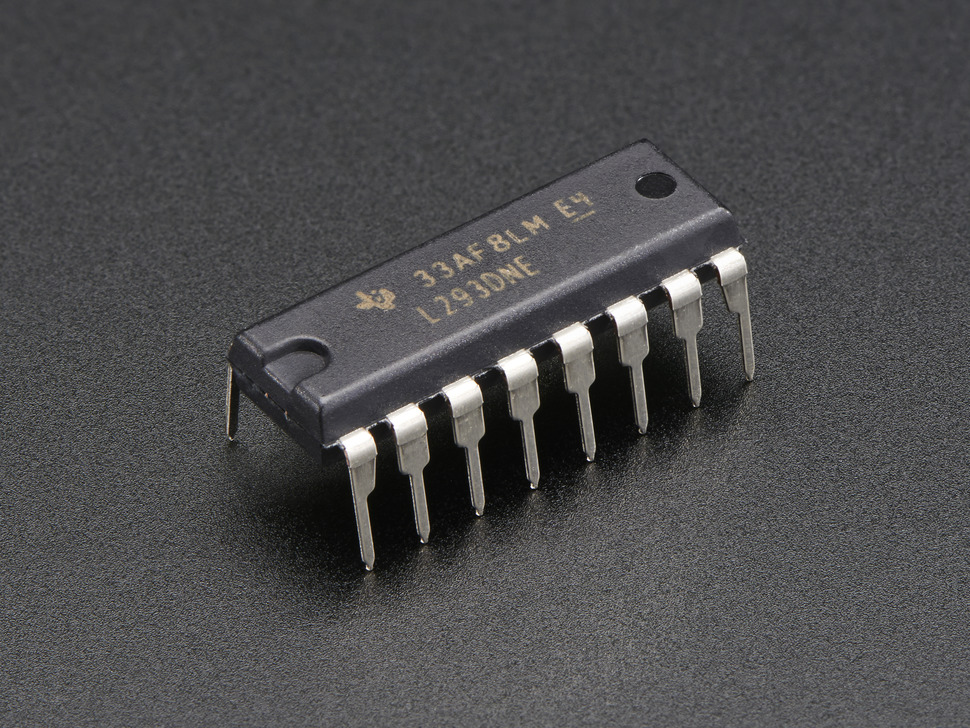
L293D is a simply a Motor Driver IC which allows DC motor to drive on either direction. L293D is a 16-pin IC which can control a set of two DC motors simultaneously in any direction. It means that you can control two DC Motor with a single L293D IC. The L293D can drive small and quiet big motors as well,.
You can Buy L293D IC in any electronic shop very easily and it costs around 60 Rupees (INR) or around 1 $ Dollar (approx Cost) or even lesser cost. You can find the necessary pin diagram, working, a circuit diagram, Logic description and Project as you read through.
Note: To Download all the files related to this tutorial CLICK HERE .
About Pin Configuration
This is the most important part of this tutorial believe me if you understand this you can easily use this IC according to your requirement whenever you want . Lets just start .
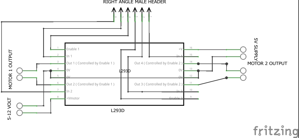
Here is a picture given below . It is a Pin diagram of L293D Ic . Click on the image for full size view.

Vcc 1(Pin no. 16): This pin is directly connected to +5 volt which is required for its internal circuit of IC . If you are using more than 5 volt you can use 7805 voltage regulator for 5 volts conversion .
Vcc 2(Pin no. 8): This pin is connected to voltage source according to your motors voltage requirement . Let us say you are using motor that requires 9 Volt than you have to connect voltage source of 9 volt to this pin .
GND(Pin no. 4,5,12,13): These pins are interconnected internally so no need of attaching all the pins to ground(Zero Volt). You can choose any pin from these 4 pins and connect to ground. Negative terminal of both power supply (one of motor and one of ICs 5 volt).
Enable 1,2&3,4(Pin no. 1,9):These pins are very useful we can call these pins as Speed controlling pins. These 2 pins helps us to control the speed of both the motors individually if . Enable 1,2 means this pin(1) have the control over 2 output pins(3,6) means one motor .Similarly Enable 3,4 have control over another motor . When you connect this pins directly to 5 volt than your motor will rotate at its full speed and if you connect it with 2.5 volt than motor will rotate at its half speed and if no voltage is connected to these pins than motor their will be no rotation . And in case of Arduino & microcontroller speed of motors will be control with the help of PWM(Pulse width modulation) .
Input 1,2 & 3,4(Pins 2,7,10,15): These pins are used to control the direction of motors clockwise as well as anticlockwise . These pins in actual changes the polarity of output pins . And Input 1,2 is for one motor and and input 3,4 is for second motor . Lets see the truth table it helps you to understand how it changes the direction of motor
| Input 1 | Input 2 | Output 1 | Output 2 | |
| LOW | LOW | NIL | NIL | |
| HIGH | LOW | (+)positive | (-)Negative | |
| LOW | HIGH | (-)Negative | (+)positive | |
| HIGH | HIGH | NIL | NIL |
Now you can Easily understand how its direction is changed with polarity and input .
Output 1,2 & 3,4(Pin no. 3,6,11,14): These pins are Connected to motors Pin 3,6 to one motor and Pin 11,14 to another one . Maximum current rating of L293D IC output is 600 mA .
Circuit for Testing It Without Arduino
Materials Required:
- L293D IC OR motor shield
- 2 Motors
- 9V battery
- 4 momentary switches
- 7805 IC
- Breadboard
- Connecting wires
Now connect everything as shown in diagram.
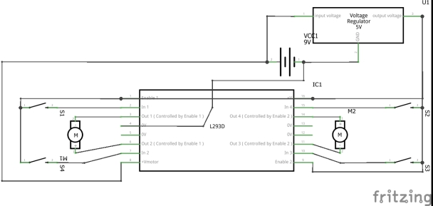
- Test circuit of L293D without arduino or microcontroller


Now to test the circuit you just have to press the buttons .
Test it with Arduino
In order to test you have to burn the following code given below and you can also download every thing from HERE. And do the following connections as shown in pictures below .


Now upload the following code on arduino you can change the speed of motors by changing this value of “analogWrite(E1, 153); ” 153 to any from 0 to 255 in arduino code for changing the speed of motors . You can also download from HERE.
#define E1 10 // Enable Pin for motor 1
#define E2 11 // Enable Pin for motor 2
#define I1 8 // Control pin 1 for motor 1 You can change any pin according to your need
#define I2 9 // Control pin 2 for motor 1
#define I3 12 // Control pin 1 for motor 2
#define I4 13 // Control pin 2 for motor 2void setup() {
pinMode(E1, OUTPUT);
pinMode(E2, OUTPUT);pinMode(I1, OUTPUT);
pinMode(I2, OUTPUT);
pinMode(I3, OUTPUT);
pinMode(I4, OUTPUT);
}void loop() {
analogWrite(E1, 153); // Run in half speed (you can control the speed of motor M1 by changing values from 0 to 255)
analogWrite(E2, 255); // Run in full speed(you can control the speed of motor M2 by changing values from 0 to 255)digitalWrite(I1, HIGH);
digitalWrite(I2, LOW);
digitalWrite(I3, HIGH);
digitalWrite(I4, LOW);delay(10000);
// change direction
digitalWrite(E1, LOW);
digitalWrite(E2, LOW);delay(200);
analogWrite(E1, 255); // Run in full speed(you can control the speed of motor M2 by changing values from 0 to 255)
analogWrite(E2, 153); // Run in half speed (you can control the speed of motor M1 by changing values from 0 to 255)digitalWrite(I1, LOW);
digitalWrite(I2, HIGH);
digitalWrite(I3, LOW);
digitalWrite(I4, HIGH);delay(10000);
}
Make your own motor driver shield
You can make your own driver circuit is given below you can design your own pcb or you can make it on perfboard as I made in less than 30 min and you can use anywhere instantly . circuit is given below.
Materials Required
- L293D IC
- Perfboard
- Screw Terminals
- Right angle Male headers 6 pin
- One IC base 16 pin
- other things like soldering iron and other stuffs etc.

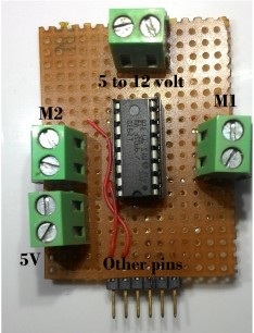
This is my motor driver shield which I have made in less then 30 minutes so this is the last step it’s all done. You can download all files including arduino code all pictures in pdf as well as jpg format from HERE. Hope you like this post and fell free to ask anything in comment section regarding this post .

Nyc blog
so many info. Is der
gud keep gng 😊
LikeLiked by 1 person
Thanks
LikeLike
A great tutorial for electronic lovers. Everything you did was accurate and is clearly understandable, as well. Keep posting these kind of stuffs.
LikeLiked by 1 person
Quite Interesting. Nice efforts.
LikeLiked by 1 person
Thanks Nikita for the appreciation
LikeLike
Nice blog….
Creative……
LikeLiked by 1 person
Thanks
LikeLike
mind blowing work u done there..
very nice.. it’s appreciable…
LikeLiked by 1 person
Thanks for your appreciation 🙂
LikeLike
How about controlling 4DC motors using 2 L293D IC’s.Is it possible or is it Safe using with Arduino?
4DC motors are 6v DC motors and Arduino UNO.
LikeLike
Yes, you can control 4 motors also without any hassle using one Arduino UNO. because control pins of l293D do not consume much current .
Hope this will help you
LikeLike